Recently I have done a project on making remote control car with 3 wheels (Two side wheels and one caster wheel).
Project duration: 30 minutes
Estimated cost: 2000 INR
The components for this project:


There are two Enable pins on l293d. Pin 1 and pin 9, for being able to drive the motor, the pin 1 and 9 need to be high. For driving the motor with left H-bridge you need to enable pin 1 to high. And for right H-Bridge you need to make the pin 9 to high. If anyone of the either pin1 or pin9 goes low then the motor in the corresponding section will suspend working. It’s like a switch.
here are 4 input pins for l293d, pin 2,7 on the left and pin 15 ,10 on the right as shown on the pin diagram. Left input pins will regulate the rotation of motor connected across left side and right input for motor on the right hand side. The motors are rotated on the basis of the inputs provided across the input pins as LOGIC 0 or LOGIC 1.
• Pin 2 = Logic 0 and Pin 7 = Logic 0 | Idle [No rotation] [Hi-Impedance state]
• Pin 2 = Logic 1 and Pin 7 = Logic 1 | Idle [No rotation]
Circuit diagram

Concept of Rf transmitter and receiver
The RF module, as the name suggests, operates at Radio Frequency. The corresponding frequency range varies between 30 kHz & 300 GHz. In this RF system, the digital data is represented as variations in the amplitude of carrier wave. This kind of modulation is known as Amplitude Shift Keying (ASK).
Transmission through RF is better than IR (infrared) because of many reasons. Firstly, signals through RF can travel through larger distances making it suitable for long range applications. Also, while IR mostly operates in line-of-sight mode, RF signals can travel even when there is an obstruction between transmitter & receiver. Next, RF transmission is more strong and reliable than IR transmission. RF communication uses a specific frequency unlike IR signals which are affected by other IR emitting sources.
This RF module comprises of an RF Transmitter and an RF Receiver. The transmitter/receiver (Tx/Rx) pair operates at a frequency of 434 MHz. An RF transmitter receives serial data and transmits it wireless through RF through its antenna connected at pin4. The transmission occurs at the rate of 1 Kbps -10 kbps. The transmitted data is received by an RF receiver operating at the same frequency as that of the transmitter.
The RF module is often used along with a pair of encoder/decoder.
Pin Diagram

Concept of Decoder and Encoder
Precautions while working on the project
Project duration: 30 minutes
Estimated cost: 2000 INR
The components for this project:
- L293D IC(H Bridge motor driver circuit)
- Two wheels & a Castor wheel
- Jumper wires
- RF transmitter and Receiver (434 MHz)
- Metal chassis
- Battery (9V) 2 Nos
- Decoder
- Encoder with Tactile switches
Tools
- Multi meter
- Soldering iron
- Screws
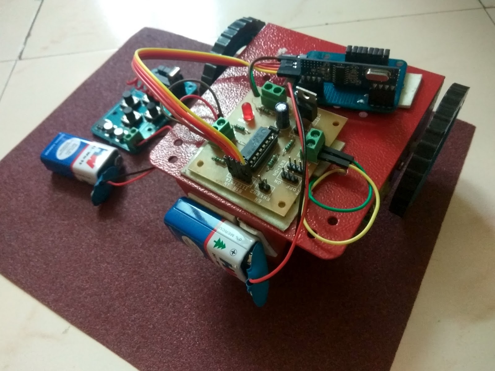
Image of the final remote car
The below picture shows top view of the remote car.
The below image shows front view of car

The below image shows side view of remote car.

Concept of l293d IC
It works on the concept of H-bridge. H-bridge is a circuit which allows the voltage to be flown in either direction. As you know voltage need to change its direction for being able to rotate the motor in clockwise or anticlockwise direction, Hence H-bridge IC are ideal for driving a DC motor.
In a single L293D chip there are two h-Bridge circuit inside the IC which can rotate two dc motor independently. Due its size it is very much used in robotic application for controlling DC motors. Given below is the pin diagram of a L293D motor controller.

TIP: you can simply connect the pin16 VCC (5v) to pin 1 and pin 9 to make them high.
L293d Logic Table
Lets consider a Motor connected on left side output pins (pin 3,6). For rotating the motor in clockwise direction the input pins has to be provided with Logic 1 and Logic 0.
• Pin 2 = Logic 1 and Pin 7 = Logic 0 | Clockwise Direction
• Pin 2 = Logic 0 and Pin 7 = Logic 1 | Anticlockwise Direction• Pin 2 = Logic 0 and Pin 7 = Logic 0 | Idle [No rotation] [Hi-Impedance state]
• Pin 2 = Logic 1 and Pin 7 = Logic 1 | Idle [No rotation]
Circuit diagram

Concept of Rf transmitter and receiver
The RF module, as the name suggests, operates at Radio Frequency. The corresponding frequency range varies between 30 kHz & 300 GHz. In this RF system, the digital data is represented as variations in the amplitude of carrier wave. This kind of modulation is known as Amplitude Shift Keying (ASK).
Transmission through RF is better than IR (infrared) because of many reasons. Firstly, signals through RF can travel through larger distances making it suitable for long range applications. Also, while IR mostly operates in line-of-sight mode, RF signals can travel even when there is an obstruction between transmitter & receiver. Next, RF transmission is more strong and reliable than IR transmission. RF communication uses a specific frequency unlike IR signals which are affected by other IR emitting sources.
This RF module comprises of an RF Transmitter and an RF Receiver. The transmitter/receiver (Tx/Rx) pair operates at a frequency of 434 MHz. An RF transmitter receives serial data and transmits it wireless through RF through its antenna connected at pin4. The transmission occurs at the rate of 1 Kbps -10 kbps. The transmitted data is received by an RF receiver operating at the same frequency as that of the transmitter.
The RF module is often used along with a pair of encoder/decoder.

Pin Description
RF Transmitter
Pin No
|
Function
|
Name
|
1
|
Ground (0V)
|
Ground
|
2
|
Serial data input pin
|
Data
|
3
|
Supply voltage; 5V
|
Vcc
|
4
|
Antenna output pin
|
ANT
|
RF Receiver
Pin No
|
Function
|
Name
|
1
|
Ground (0V)
|
Ground
|
2
|
Serial data output pin
|
Data
|
3
|
Linear output pin; not connected
|
NC
|
4
|
Supply voltage; 5V
|
Vcc
|
5
|
Supply voltage; 5V
|
Vcc
|
6
|
Ground (0V)
|
Ground
|
7
|
Ground (0V)
|
Ground
|
8
|
Antenna input pin
|
ANT
|
Concept of Decoder and Encoder
The HT 12E Encoder ICs are series of CMOS LSIs for Remote Control system applications. They are capable of Encoding 12 bit of information which consists of N address bits and 12-N data bits. Each address/data input is externally trinary programmable if bonded out.
The HT 12D ICs are series of CMOS LSIs for remote control system applications. This ICs are paired with each other. For proper operation a pair of encoder/decoder with the same number of address and data format should be selected. The Decoder receive the serial address and data from its corresponding decoder, transmitted by a carrier using an RF transmission medium and gives output to the output pins after processing the data.
The HT 12D ICs are series of CMOS LSIs for remote control system applications. This ICs are paired with each other. For proper operation a pair of encoder/decoder with the same number of address and data format should be selected. The Decoder receive the serial address and data from its corresponding decoder, transmitted by a carrier using an RF transmission medium and gives output to the output pins after processing the data.
- Always test with low voltage
- Soldering connection should be clean and tight
- Wheels should be fixed properly
- Soldered joints should not touch metal chassis
- Voltage regulators should be checked using multi-meter
The next part is integrating this project with Mobile App control.
Note: We are working on this once done it will be updated here.
No comments:
Post a Comment