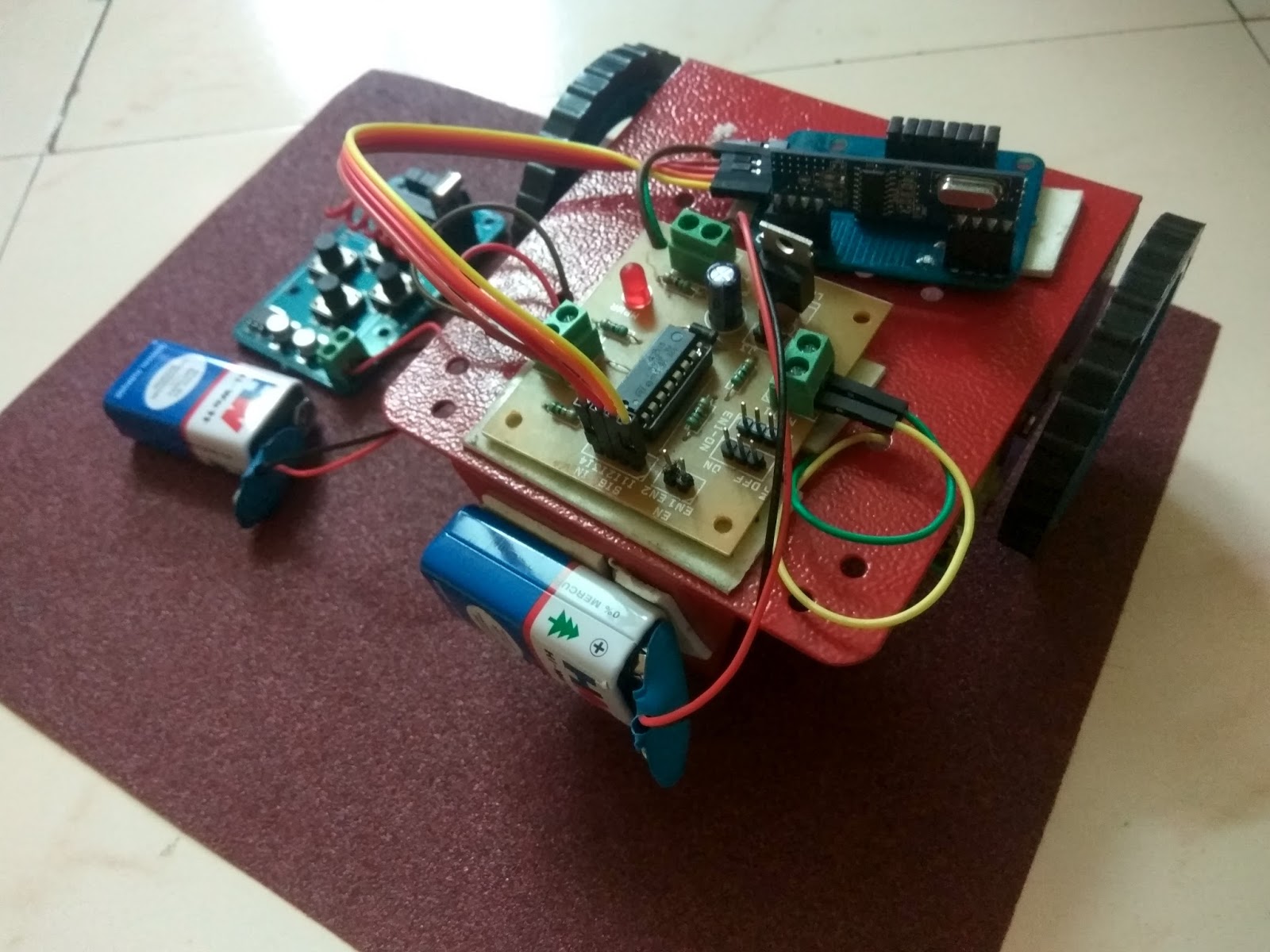
This project basically fingerprint based locking mechanism.It is developed by using Arduino Uno board and fingerprint scanner R307.
This project is based on IoT concept. I have developed this mini project to incorporate Internet of Things ideas. The specialty in this project is using multiple devices connected to locking or unlocking mechanism of door.
I am going to explain in this project on 3 stages.
Components required
- R307 fingerprint scanner
- 360 degree servo motor
- Arduino Uno
- Jumper wires
Circuit Diagram

- Red wire +5 v
- Brown wire - Gnd
- Yellow wire - Arduino 9(PWM)
Pin Diagram of R307 fingerprint scanner
- Red wire - Vin( in Arduino)
- Black wire - Gnd
- Yellow wire - 2 (digital in Arduino)
- White wire - 3(digital in Arduino)
Program the arduino using Ardunio software
Include Adafruit fingerprint library in to your ardunio software
Code to enroll a fingerprint

- Red wire - Vin( in Arduino)
- Black wire - Gnd
- Yellow wire - 2 (digital in Arduino)
- White wire - 3(digital in Arduino)
Program the arduino using Ardunio software
Include Adafruit fingerprint library in to your ardunio software
Code to enroll a fingerprint
            /***************************************************
  This is an example sketch for our optical Fingerprint sensor

  Designed specifically to work with the Adafruit BMP085 Breakout
  ----> http://www.adafruit.com/products/751

  These displays use TTL Serial to communicate, 2 pins are required to
  interface
  Adafruit invests time and resources providing this open source code,
  please support Adafruit and open-source hardware by purchasing
  products from Adafruit!

  Written by Limor Fried/Ladyada for Adafruit Industries.
  BSD license, all text above must be included in any redistribution
 ****************************************************/

#include

// On Leonardo/Micro or others with hardware serial, use those! #0 is green wire,
//#1 is white
// uncomment this line:
// #define mySerial Serial1

// For UNO and others without hardware serial, we must use software serial...
// pin #2 is IN from sensor (GREEN wire)
// pin #3 is OUT from arduino  (WHITE wire)
// comment these two lines if using hardware serial
#include
SoftwareSerial mySerial(2, 3);

Adafruit_Fingerprint finger = Adafruit_Fingerprint(&mySerial);

uint8_t id;

void setup()
{
  Serial.begin(9600);
  while (!Serial);  // For Yun/Leo/Micro/Zero/...
  delay(100);
  Serial.println("\n\nAdafruit Fingerprint sensor enrollment");

  // set the data rate for the sensor serial port
  finger.begin(57600);

  if (finger.verifyPassword()) {
    Serial.println("Found fingerprint sensor!");
  } else {
    Serial.println("Did not find fingerprint sensor :(");
    while (1) { delay(1); }
  }
}

uint8_t readnumber(void) {
  uint8_t num = 0;

  while (num == 0) {
    while (! Serial.available());
    num = Serial.parseInt();
  }
  return num;
}

void loop()                     // run over and over again
{
  Serial.println("Ready to enroll a fingerprint!");
  Serial.println("Please type in the ID # (from 1 to 127) you want to save this finger as...");
  id = readnumber();
  if (id == 0) {// ID #0 not allowed, try again!
     return;
  }
  Serial.print("Enrolling ID #");
  Serial.println(id);

  while (!  getFingerprintEnroll() );
}

uint8_t getFingerprintEnroll() {

  int p = -1;
  Serial.print("Waiting for valid finger to enroll as #"); Serial.println(id);
  while (p != FINGERPRINT_OK) {
    p = finger.getImage();
    switch (p) {
    case FINGERPRINT_OK:
      Serial.println("Image taken");
      break;
    case FINGERPRINT_NOFINGER:
      Serial.println(".");
      break;
    case FINGERPRINT_PACKETRECIEVEERR:
      Serial.println("Communication error");
      break;
    case FINGERPRINT_IMAGEFAIL:
      Serial.println("Imaging error");
      break;
    default:
      Serial.println("Unknown error");
      break;
    }
  }

  // OK success!

  p = finger.image2Tz(1);
  switch (p) {
    case FINGERPRINT_OK:
      Serial.println("Image converted");
      break;
    case FINGERPRINT_IMAGEMESS:
      Serial.println("Image too messy");
      return p;
    case FINGERPRINT_PACKETRECIEVEERR:
      Serial.println("Communication error");
      return p;
    case FINGERPRINT_FEATUREFAIL:
      Serial.println("Could not find fingerprint features");
      return p;
    case FINGERPRINT_INVALIDIMAGE:
      Serial.println("Could not find fingerprint features");
      return p;
    default:
      Serial.println("Unknown error");
      return p;
  }

  Serial.println("Remove finger");
  delay(2000);
  p = 0;
  while (p != FINGERPRINT_NOFINGER) {
    p = finger.getImage();
  }
  Serial.print("ID "); Serial.println(id);
  p = -1;
  Serial.println("Place same finger again");
  while (p != FINGERPRINT_OK) {
    p = finger.getImage();
    switch (p) {
    case FINGERPRINT_OK:
      Serial.println("Image taken");
      break;
    case FINGERPRINT_NOFINGER:
      Serial.print(".");
      break;
    case FINGERPRINT_PACKETRECIEVEERR:
      Serial.println("Communication error");
      break;
    case FINGERPRINT_IMAGEFAIL:
      Serial.println("Imaging error");
      break;
    default:
      Serial.println("Unknown error");
      break;
    }
  }

  // OK success!

  p = finger.image2Tz(2);
  switch (p) {
    case FINGERPRINT_OK:
      Serial.println("Image converted");
      break;
    case FINGERPRINT_IMAGEMESS:
      Serial.println("Image too messy");
      return p;
    case FINGERPRINT_PACKETRECIEVEERR:
      Serial.println("Communication error");
      return p;
    case FINGERPRINT_FEATUREFAIL:
      Serial.println("Could not find fingerprint features");
      return p;
    case FINGERPRINT_INVALIDIMAGE:
      Serial.println("Could not find fingerprint features");
      return p;
    default:
      Serial.println("Unknown error");
      return p;
  }

  // OK converted!
  Serial.print("Creating model for #");  Serial.println(id);

  p = finger.createModel();
  if (p == FINGERPRINT_OK) {
    Serial.println("Prints matched!");
  } else if (p == FINGERPRINT_PACKETRECIEVEERR) {
    Serial.println("Communication error");
    return p;
  } else if (p == FINGERPRINT_ENROLLMISMATCH) {
    Serial.println("Fingerprints did not match");
    return p;
  } else {
    Serial.println("Unknown error");
    return p;
  }

  Serial.print("ID "); Serial.println(id);
  p = finger.storeModel(id);
  if (p == FINGERPRINT_OK) {
    Serial.println("Stored!");
  } else if (p == FINGERPRINT_PACKETRECIEVEERR) {
    Serial.println("Communication error");
    return p;
  } else if (p == FINGERPRINT_BADLOCATION) {
    Serial.println("Could not store in that location");
    return p;
  } else if (p == FINGERPRINT_FLASHERR) {
    Serial.println("Error writing to flash");
    return p;
  } else {
    Serial.println("Unknown error");
    return p;
  }
}
Arduino code for door lock
            /***************************************************
  This is an example sketch for our optical Fingerprint sensor

  Designed specifically to work with the Adafruit BMP085 Breakout
  ----> http://www.adafruit.com/products/751

  These displays use TTL Serial to communicate, 2 pins are required to
  interface
  Adafruit invests time and resources providing this open source code,
  please support Adafruit and open-source hardware by purchasing
  products from Adafruit!

  Written by Limor Fried/Ladyada for Adafruit Industries.
  BSD license, all text above must be included in any redistribution
 ****************************************************/


#include
#include
#include  //Add servo library

int getFingerprintIDez();

Servo servo1; //Define servo name / object

#define servoPin 9 //Define pin number to which servo motor is connected
#define durationTime 11000 //Define the time it remains in the open position of the door lock (miliseconds)
#define servoMin 180 //Open position
#define servoMax  0 // Closed position
#define servostop 90

SoftwareSerial mySerial(2, 3);
Adafruit_Fingerprint finger = Adafruit_Fingerprint(&mySerial);


void setup()
{
  while (!Serial);  // For Yun/Leo/Micro/Zero/...

  Serial.begin(9600);
  Serial.println("Adafruit finger detect test");

  servo1.attach(servoPin); //Define pin number of the servo
   //The position of the servo at the start of the program

  // set the data rate for the sensor serial port
  finger.begin(57600);

  if (finger.verifyPassword()) {
    Serial.println("Found fingerprint sensor!");
  } else {
    Serial.println("Did not find fingerprint sensor :(");
    while (1);
  }
  Serial.println("Waiting for valid finger...");
}

void loop()                     // run over and over again
{
  getFingerprintIDez();
  delay(50);            //don't ned to run this at full speed.
}

uint8_t getFingerprintID() {
  uint8_t p = finger.getImage();
  switch (p) {
    case FINGERPRINT_OK:
      Serial.println("Image taken");
      break;
    case FINGERPRINT_NOFINGER:
      Serial.println("No finger detected");
      return p;
    case FINGERPRINT_PACKETRECIEVEERR:
      Serial.println("Communication error");
      return p;
    case FINGERPRINT_IMAGEFAIL:
      Serial.println("Imaging error");
      return p;
    default:
      Serial.println("Unknown error");
      return p;
  }

  // OK success!

  p = finger.image2Tz();
  switch (p) {
    case FINGERPRINT_OK:
      Serial.println("Image converted");
      break;
    case FINGERPRINT_IMAGEMESS:
      Serial.println("Image too messy");
      return p;
    case FINGERPRINT_PACKETRECIEVEERR:
      Serial.println("Communication error");
      return p;
    case FINGERPRINT_FEATUREFAIL:
      Serial.println("Could not find fingerprint features");
      return p;
    case FINGERPRINT_INVALIDIMAGE:
      Serial.println("Could not find fingerprint features");
      return p;
    default:
      Serial.println("Unknown error");
      return p;
  }

  // OK converted!
  p = finger.fingerFastSearch();
  if (p == FINGERPRINT_OK) {
    Serial.println("Found a print match!");
  } else if (p == FINGERPRINT_PACKETRECIEVEERR) {
    Serial.println("Communication error");
    return p;
  } else if (p == FINGERPRINT_NOTFOUND) {
    Serial.println("Did not find a match");
    return p;
  } else {
    Serial.println("Unknown error");
    return p;
  }

  // found a match!
  Serial.print("Found ID #"); Serial.print(finger.fingerID);
  Serial.print(" with confidence of "); Serial.println(finger.confidence);
}

// returns -1 if failed, otherwise returns ID #
int getFingerprintIDez() {
  uint8_t p = finger.getImage();
  if (p != FINGERPRINT_OK)  return -1;

  p = finger.image2Tz();
  if (p != FINGERPRINT_OK)  return -1;

  p = finger.fingerFastSearch();
  if (p != FINGERPRINT_OK)  return -1;

  servo1.write(servoMin); //If the fingerprint is correct open the door lock
  delay(6000); //Keep the lock open for the defined duration
  servo1.write(servostop);
  delay(6000);
  servo1.write(servoMax);//take the lock OFF again
  delay(durationTime);
  servo1.write(servostop);


  // found a match!
  Serial.print("Found ID #"); Serial.print(finger.fingerID);
  Serial.print(" with confidence of "); Serial.println(finger.confidence);
  return finger.fingerID;
}
Make the connections as shown in the circuit diagram ,using the pin numbers provided above